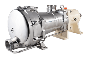
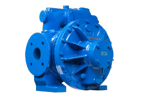
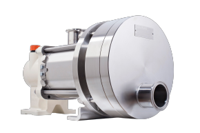
How eccentric Disc pumps work
Unlike other pump technologies, the eccentric disc pump combines rotary motion with volumetric precision, ensuring constant flow regardless of pressure changes, making it ideal for industries like chemical processing, food and beverage, cosmetics, and energy.
Main Components
An eccentric disc pump consists of:
-
Eccentric shaft: The drive shaft mounted off-centre (eccentrically) to create a wobbling motion.
-
Disc: A circular pumping element connected to the eccentric shaft, forming sealed chambers as it rotates.
-
Pump body (liner): A stationary, circular chamber that houses the disc.
-
Inlet and outlet ports: Openings through which the fluid enters and exits.
-
Head plates and bearings: Support components ensuring alignment and smooth operation.
Working Principle (Detailed)
The operation of an eccentric disc pump is based on the movement of an eccentrically mounted disc inside a circular casing, which creates a series of expanding and contracting chambers to draw in and discharge fluid continuously.
1. Eccentric Motion
As the motor rotates the eccentric shaft, the disc mounted on it moves in a circular but off-centre path. This motion causes one side of the disc to come closer to the pump wall while the opposite side moves away — generating alternating zones of expanding and contracting volume.
2. Suction Phase (Filling the Chamber)
-
When the disc moves away from the pump casing, a vacuum is created on the suction side.
-
This pressure drop draws liquid into the expanding cavity through the inlet port.
-
The sealed contact between the disc and the liner prevents backflow or slippage.
3. Transfer Phase (Trapped Volume Movement)
-
As the disc continues to rotate, the fluid trapped in the chamber is carried around the inner wall of the pump casing.
-
The geometry ensures a completely sealed transfer of the fluid with no internal bypass, resulting in accurate, volumetric displacement.
4. Discharge Phase (Compression and Delivery)
-
On the opposite side of the rotation, the space between the disc and casing decreases.
-
This compression forces the trapped fluid out through the discharge port at a constant, pulse-free rate.
-
Because of the pump’s internal sealing, each revolution displaces the same volume, independent of discharge pressure or viscosity.
This continuous cycle produces a smooth, low-shear flow — ideal for sensitive products and applications where flow accuracy and product integrity are critical.
Hydraulic and Mechanical Characteristics
-
Flow Type: Non-pulsating, linear, and directly proportional to speed.
-
Pressure Capability: Up to 10 bar (liquid transfer) or higher for specific models.
-
Suction Lift: Self-priming, typically up to 9 m depending on viscosity.
-
Viscosity Range: Handles fluids from less than 1 cP to over 100,000 cP.
-
Direction: Reversible – flow direction can be changed by reversing motor rotation.

