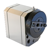
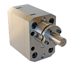
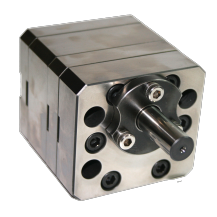
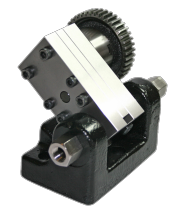
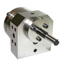
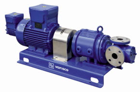
How External gear pumps work
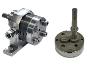
External gear pumps are positive displacement pumps that use two precisely machined, intermeshing gears to transfer fluid. They are commonly used for hydraulic systems, lubrication, fuel transfer, and chemical dosing where consistent, pulseless flow and high pressure are required.
Operating Principle
Step-by-Step Working Principle
1. Suction Phase (Fluid Entry)
As the gears rotate, their teeth disengage on the suction side of the pump. This increases the volume between the teeth and the casing, creating a partial vacuum.
-
The pressure drop draws liquid into the spaces between the gear teeth.
-
The tight clearances prevent backflow of fluid into the inlet.
2. Transfer Phase (Fluid Conveyance)
Once the fluid is trapped between the gear teeth and the pump casing, it is carried around the outside of both gears toward the discharge side.
-
There is no flow through the center of the pump because the gears are tightly meshed there.
-
The liquid remains sealed within the gear cavities and casing, ensuring minimal leakage or slippage.
3. Discharge Phase (Fluid Delivery)
On the discharge side, the gear teeth re-engage (mesh), decreasing the volume between them.
-
This mechanical action forces the trapped liquid out through the discharge port.
-
Because this happens continuously with each gear rotation, the pump produces a smooth and consistent flow.
The amount of fluid delivered per revolution is fixed by the gear geometry and clearances, meaning the pump provides precise, repeatable flow proportional to its speed.
Key Characteristics
-
Flow direction: Constant, non-pulsating
-
Pressure capability: Up to ~250 bar (depending on size and materials)
-
Viscosity range: Handles thin to highly viscous fluids
-
Construction materials: Steel, cast iron, stainless steel, or bronze
-
Lubrication: Typically self-lubricating from the pumped fluid

