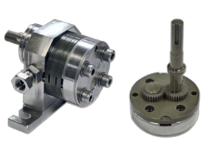
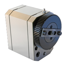
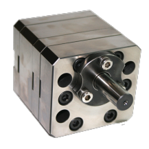
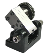
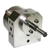
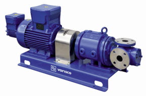
How internal gear pumps work
As the rotor (outer) gear turns, it drives the idler (inner) gear. When the idler gear comes out of contact with the rotor gear, a low-pressure zone is created. The liquid is drawn into the pump and travels along with the casing to the discharge side of the pump. The gear teeth mesh back together and force the fluid out of the pump.
Proper gear clearance is essential to the long life and efficiency of these pumps. If the clearance is too wide, pump efficiency will suffer. If pump clearance is too tight, as in the case of thermal expansion, the gears will make contact and cause damage or failure.
Unlike a centrifugal pump that cavitates against blocked discharge lines, an internal gear pump will continue to generate flow and build pressure. The pressure will continue to build until something releases it. Oftentimes, this results in a pump failure and a costly component repair or replacement.
Internal gear pumps are oftentimes equipped with an internal or external relief valve. This valve diverts flow when pressure builds in the discharge line, preventing catastrophic failure.
Their simple yet precise design allows smooth, quiet operation and the ability to handle a wide range of viscosities, making them ideal for lubrication, fuel transfer, chemical processing, and polymer handling.
Main Components
An internal gear pump typically consists of:
-
Internal (drive) gear: A large gear with teeth on the inside circumference, driven by the motor.
-
External (idler) gear: A smaller gear positioned inside the internal gear, rotating on an offset shaft.
-
Crescent: A stationary, curved partition that fills the space between the gears, maintaining separation of suction and discharge zones.
-
Pump casing and head: The housing that encloses the gears and directs fluid flow.
-
Inlet and outlet ports: Openings on opposite sides of the pump body where fluid enters and exits.
Working Principle (Detailed)
1. Suction Phase
As the internal (drive) gear rotates, it turns the smaller external (idler) gear in the opposite direction.
-
The gears disengage on the suction side, increasing the volume between the gear teeth and the pump casing.
-
This creates a partial vacuum, drawing fluid into the expanding cavities from the inlet.
2. Transfer Phase
-
The trapped fluid is carried around the crescent by both gears, confined between the gear teeth and casing.
-
The crescent partition prevents the fluid on the discharge side from returning to the suction side, maintaining directional flow.
3. Discharge Phase
-
On the discharge side, the gears re-mesh, reducing the volume between the teeth.
-
This mechanical action forces the trapped fluid out through the outlet under pressure.
-
Because the gears remain closely meshed, backflow is minimal, resulting in accurate and consistent flow delivery.
Each revolution moves a fixed volume of liquid, making the pump’s output directly proportional to its speed—ideal for metering or dosing applications.
Key Characteristics
-
Flow Type: Smooth, non-pulsating, and directly proportional to speed.
-
Pressure Capability: Typically up to 14–17 bar (higher for specialized models).
-
Viscosity Range: From low-viscosity fuels to highly viscous oils or polymers (up to 1,000,000 cP).
-
Direction of Flow: Reversible by reversing drive rotation.
-
Self-Priming: Excellent suction lift due to tight internal clearances.

